
Build a wooden rotisserie
By now many of you have seen my wooden rotisserie and have asked for build plans. So here they are!
I built mine for about $160 (in 2022 dollars) and it took me about 8 hours in total including building, removing the tub and mounting.
Materials
Wood:
4x4x10’ – 1
4x4x8’ – 2
4x4x6’ – 2
2x4x8’ – 2
Tools:
Circular Saw
Chisel
Socket Set
Drill
3/8” Drill Bit
1-1/4” Spade Bit / Hole Saw
Hardware:
3/8-in x 8-in Gray Hot-Dipped Galvanized Hex-Head Exterior Lag Screws – 4 3/8-in x 2-in Gray Hot-Dipped Galvanized Hex-Head Exterior Lag Screws – 4 3/8-in x 8-in Galvanized Coarse Thread Exterior Carriage Bolt – 2
3/8-In Washers – 12
3/8-In Steel Nuts – 6
#12 x 2” Wood Screws – 8
#10 x 3” Wood Screws – 12
#10 x 1-3/4” Wood Screws – 24
3/4-in ID x 10” Steel Pipe / Nipple – 2
3/4-in L Black Iron Floor Flange – 2
4-In Swivel Casters – 6
I got everything from Lowe’s with the exception of the casters which I got from Harbor Freight.
This is the best I can pull from memory and should get you mostly there. The biggest thing I found that I needed more of was general wood screws. So having a handful spare is never a bad thing.
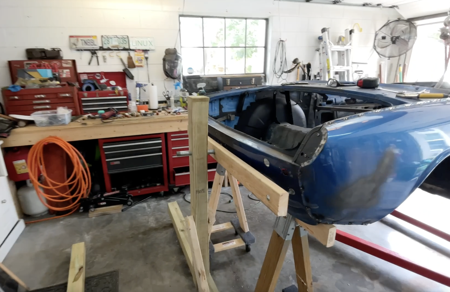
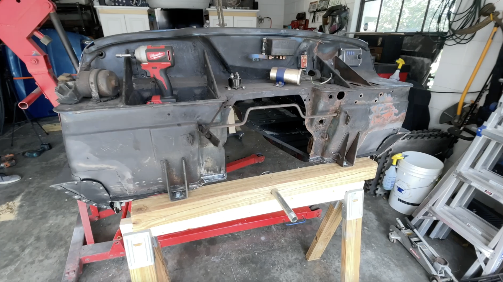
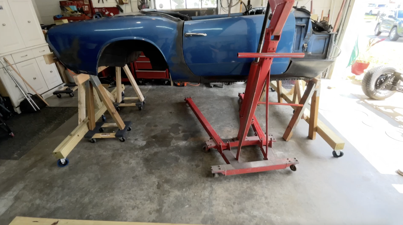
Just to preface this too. I used a cherry picker to lift the tub using the bracing I had welded in prior to doing my body work. I placed the tub on a set of sawhorses afterwards.
The Build
Uprights:
To start, I built the uprights. For this I needed one of the 4x4x8s and both of the 4x4x6s.
I cut the 4x4x8 in half which gave me two 4x4x4s.
be a tight fit. Tight enough so you can lift the whole thing as one piece without hardware. This just ensures a nice snug fit and reduces the risk of movement.
I then cut some of the 2x4s into 2’ lengths and screwed them to the upright to help add lateral support.
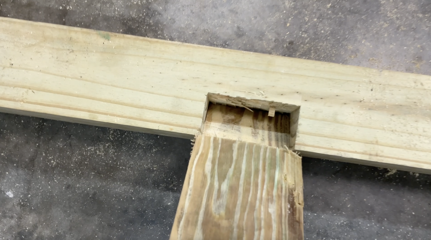
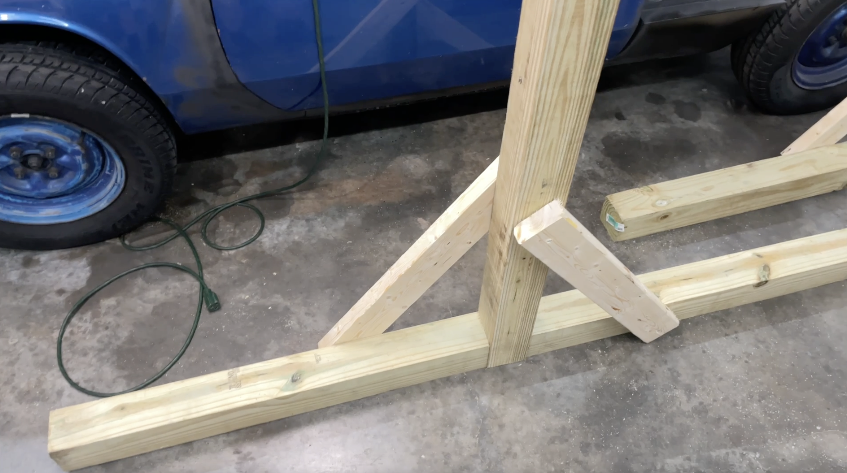
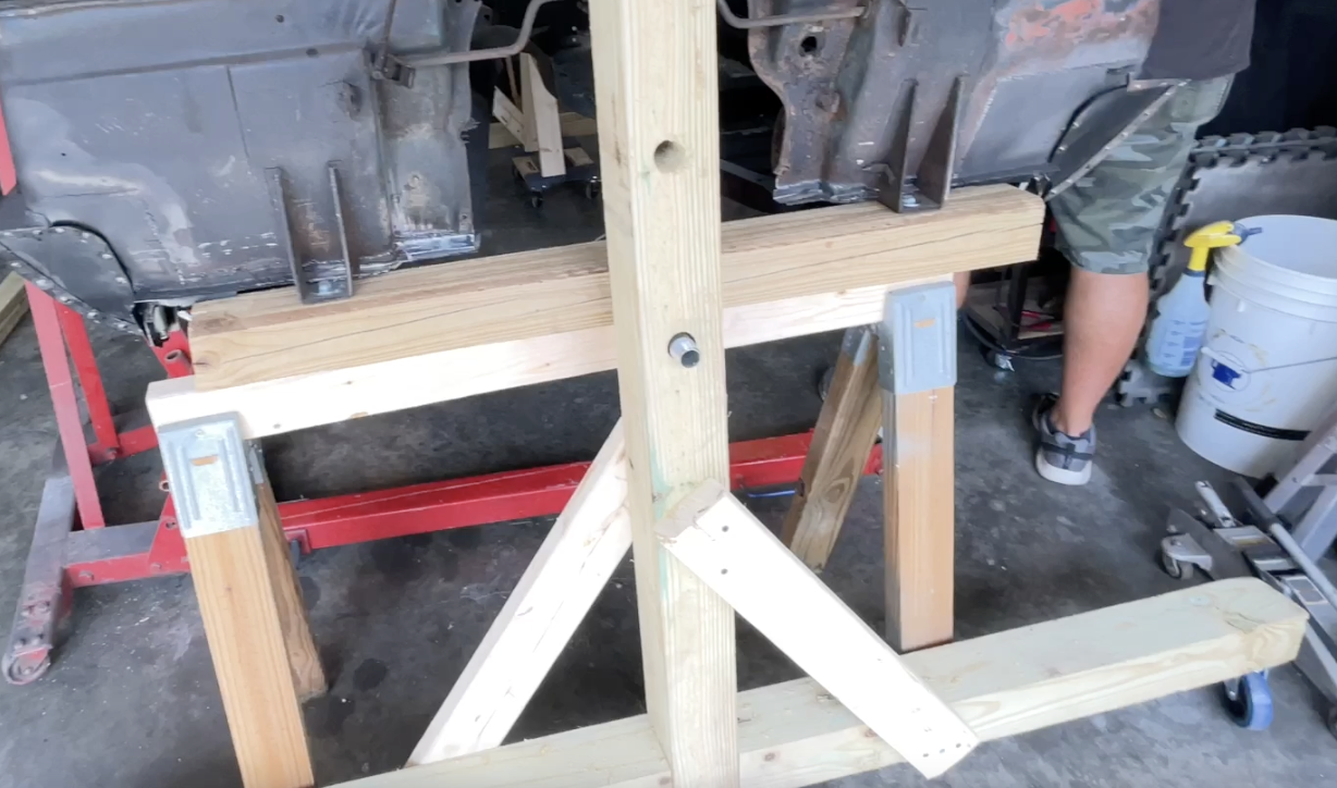
I then cut a notch into the 4x4x4 at the bottom, and then cut a corresponding notch into the 4x4x6 in the middle. This way the two will lock into one another. You want this to
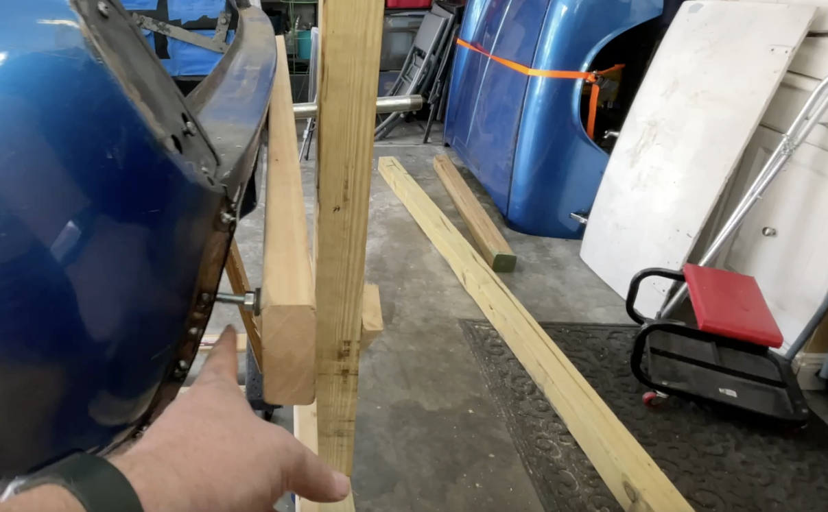
Then, I used a 1-1/4” whole saw to a hole into the uprights. I positioned this hole 3’ up from the bottom of the upright. I marked both sides of the 4x4x4 dead center and used a drill bit to pilot the hole to make sure that it was level.
Once I had the uprights built, I attached the casters. One on each side, and one in the middle below the joint of the upright and the foot. I used the #10 x 1-3/4” Wood Screws for this.
Swivels:
The swivels are pretty straight forward. Essentially you take the remaining 4x4x8 and again, cut it in half so that you have two 4x4x4s.
(On my build I used a 2x4x4 for the rear, but that is because I had it, and didn’t want to go to the store again. But if I did it again I would use a 4×4 in the back.)
another washer and nut. This now has completed the rear of the cars attachment.
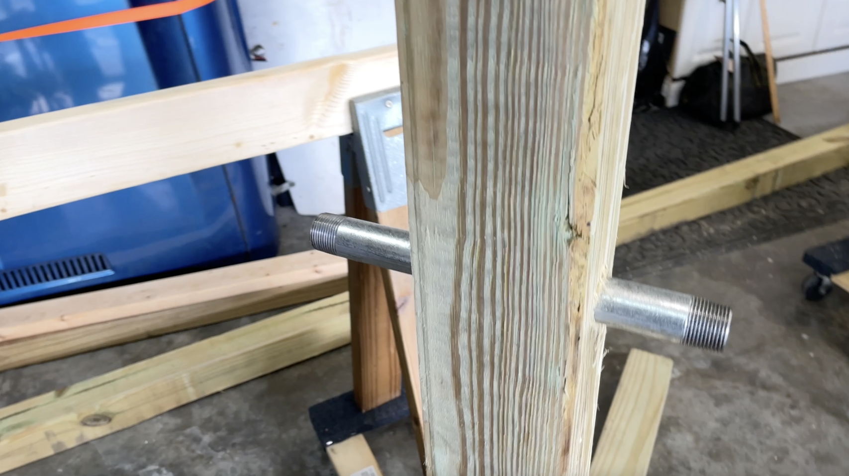
At this point then I lifted the rear of the car up off the sawhorse and put the pipe of the swivel through the hole in the upright. Because the upright is now on casters it will roll, so I sat it down on an elevated sawhorse to help secure it and keep it from going anywhere.
Once I cut them, I started by mounting the rear. I measured from the bumper mount hole on the body to bumper mount hole. I then translated this measurement to the 4x4x4 and drilled 3/8” holes through the 4×4. These holes are for the bolts that mount into the bumper mounts.
I then located center on the 4x4x4 and used the 1-1/4” hole saw again to cut a hole for the pipe / nipple.
Then I took the floor flange and I hammered it into the wood. Reason being, is that the thread only allows you to screw the pipe into it from one side only, and I wanted the pipe to go through the wood instead of bolting to the wood. So to get the flange to sit flat on the wood, I had to hammer it into place, and then I used the #12 x 2” Wood Screws to secure it. I then screwed the pipe into the nipple and made sure it was tight.
I then put the two 3/8-in x 8-in Galvanized Coarse Thread Exterior Carriage Bolt through the wood. I put a washer and nut on the car side of the wood to tighten the bolt to the wood, and then another nut and washer for the outside of the car to help tighten to the car. Then I put the assembled swivel onto the car, and secured it with yet
Onto the front.
The front is similar to the rear in the sense of finding center of the 4x4x4 and drilling a hole in it for the pipe. Hammer the flange into the wood just like the rear, and attach with the screws. Then thread the pipe into the flange ensuring it is tight.
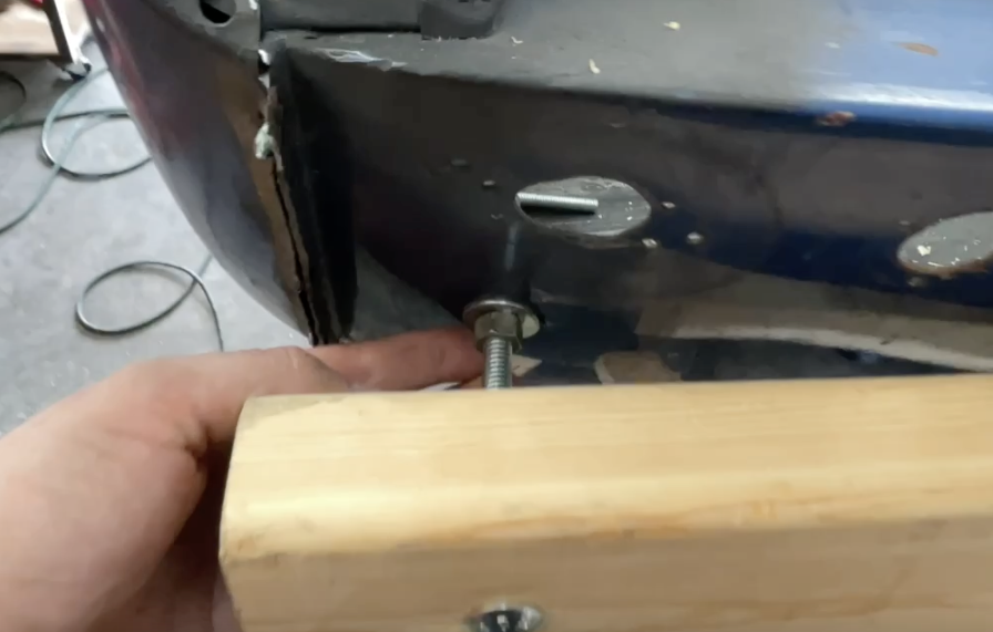
I then measured from the center of the body mount to the center of the other body mount, and transferred that measurement to the board. This is where I pre-drilled more holes for the two 3/8-in x 2-in Gray Hot-Dipped Galvanized Hex-Head Exterior Lag Screws.
Once predrilled I was able to line it up under the mounts, and bolt the body to the 4×4 with the lag screws and washers.
Then at this point I lifted the car, and put the pipe through the upright just like on the rear, then set it back down on an elevated sawhorse again for stability.
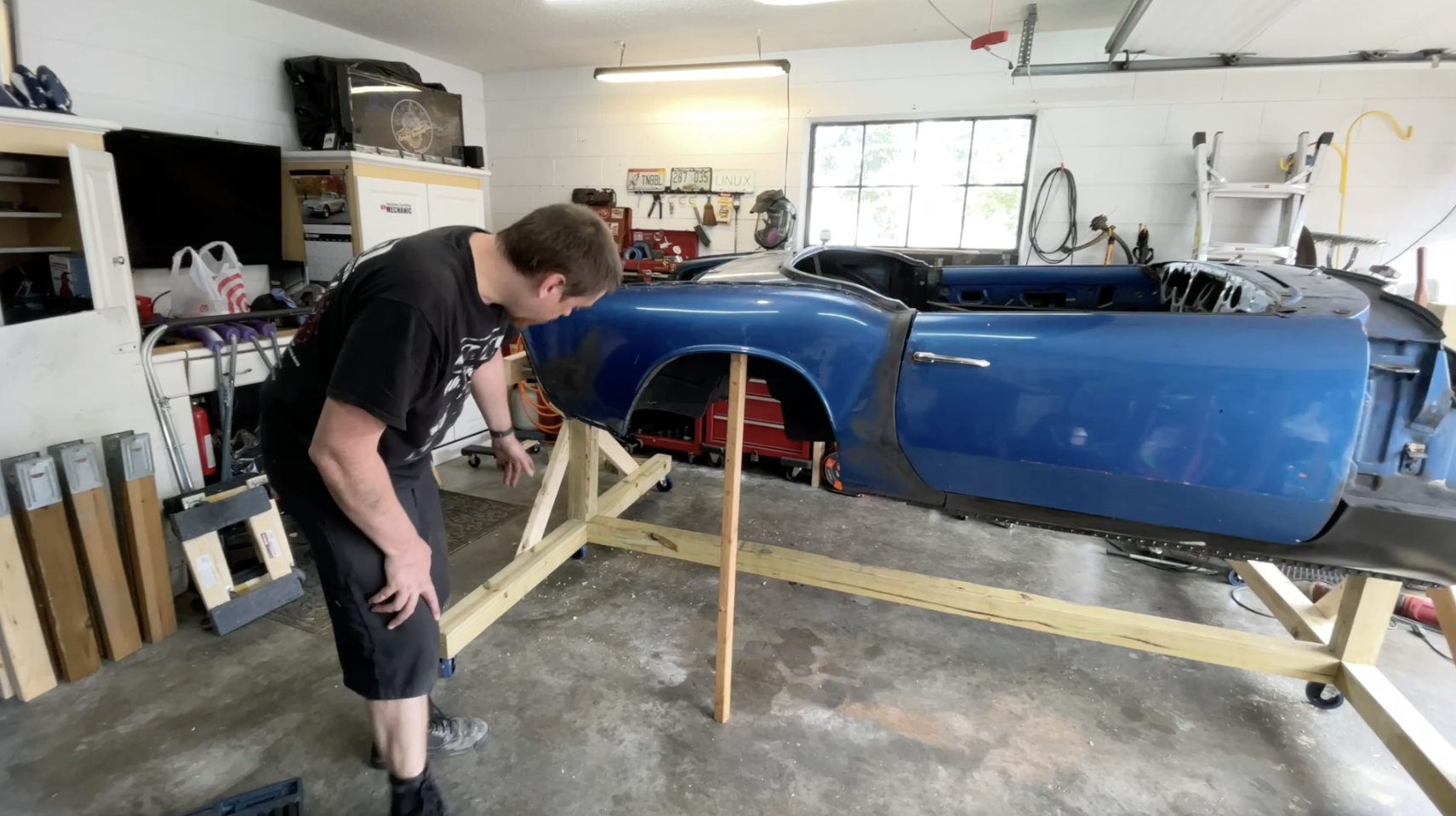
You will notice that I have two spots on the front for the pipe. The one up top is at the 3’ mark and would put the center axis parallel with the rear. But I wanted to keep the tub relatively level so I made another hole which is about 8” lower than the top one, and that is the one that I chose to go with.
Big benefit of this is that it rotates ever so slightly off center which mades the swivels hit the uprights and this allows it to act as a stop in each direction. Now if you want full rotation then you will want the center axis to be parallel.
The Center Span
So the center span is super important to measure and get correct. For me, the center span was 106 inches. Once measured I then cut the 4x4x10 to the proper length.
I piloted two holes through the center of the joint where the foot and the upright come together on either side. This ties the whole rotisserie together. Once I had this piloted, I took the cut 4×4 and screwed in the 3/8-in x 8-in Gray Hot-Dipped Galvanized Hex-Head Exterior Lag Screws with washers. I did not pilot the hole into the cross span but if I had a large enough bit I would have.
I then used an impact gun to screw one side together, and then I moved onto the other side. If the span does not close up fully, I had to back the screws out, and pull it together using a clam and a 2×4 screwed to the span to just pull it together, then I used the impact gun to screw them home.
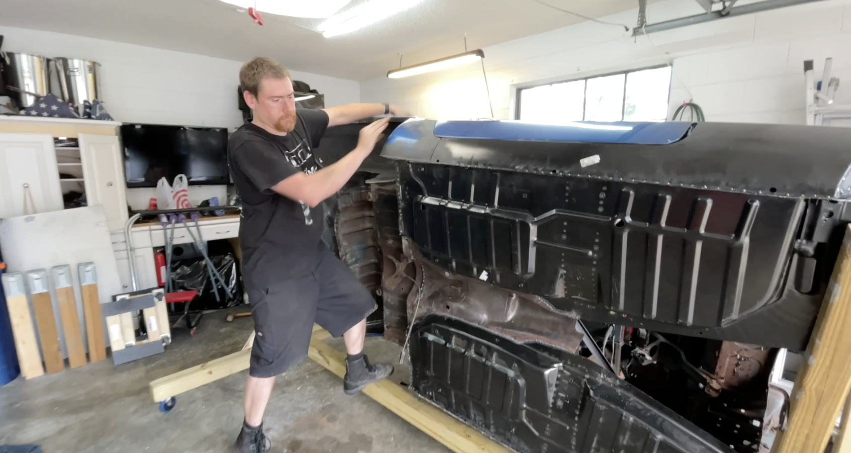
This completed the build. The car should rotate with relative ease. For me the balance was pretty much on point and it takes minimal effort to rotate it from one side to the other.
If you have questions about the build please feel free to reach out to me via email at projectcargarage@icloud.com
Also please check out my video on this build over on my YouTube Channel. https://www.youtube.com/c/StevesProjectCarGarage
Thanks and good luck!
Cheers,
Steve
Steve’s Project Car Garage